Fish Feeder Demo
Below, there is a quick demonstration video of the feeder. I recommend using sound to hear when the motor activates.
Click here to view a demo of the web interface page.
A Summary of How it Works
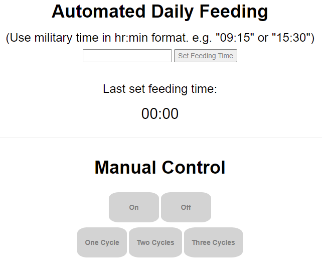
The feeder is controlled using a web interface I created, an image of which is seen on the right. The interface is fairly simple and plain, but it has all the functions I want, like setting a feeding time and manual control.
On the interface, there is a box to type in a time using military time in hr:min format. Then, by clicking the "Set Feeding Time" button, the set time is updated in Google Firebase. The set feeding time is then shown below "Last set feeding time:".
In addition to the automatic daily feeding, I added manual control. This way, I could go onto the interface website to manually feed the fish whenever I wanted to. There are "On" and "Off" buttons to continuouly run or turn off the feeder. There are also set cycle buttons to run the feeder for a set period of time. Currently, I have one cycle set to 1.5 seconds, two cycles set to 2 seconds, and three cycles set to 2.5 seconds.
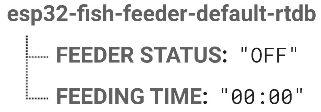
The the left is what the Firebase console looks like. When something is inputted on the web interface, it updates here. The "FEEDER STATUS" can either display "ON," "OFF," "ONE CYCLE," "TWO CYCLES," or "THREE CYCLES" for each's respective function when activated. The "FEEDING TIME" updates whenever a new time is set on the web interface. This time is stored forever until it's changed again.
Then, in the Huzzah code, I made a few lines of code that detect when the "FEEDER STATUS" and "FEEDING TIME" have changed and result in an output respective to the given input. For example, clicking the "One Cycle" button on the web interface activates the set of code for one feeding cycle.
The line of code below is line 164 in the main code page (I talk more in depth on coding later). This if() function only activates when the "FEEDER STATUS" is "ONE CYCLE." And, the only way for the "FEEDER STATUS" to show "ONE CYCLE" is for the "One Cycle" button to be pressed on the web interface. Just to note with the code below, I put ... in the if() statement here, but in the real code, it has the actual functions. I have these if() statements for all of the web interface inputs, so there is one for the set time, one for manually turning on, one for manually turning off, and three for the cycles.
if (feederStatusString == "ONE CYCLE") {    // If one cycle button is pressed, run code for feeding one cycle
...
...
}
Think of it like a chain-of-command. First, the user inputs something on the web interface, which then outputs data to Firebase. When Firebase recieves the data from the web interface, Firebase outputs that data to the Huzzah. Finally, the Huzzah recieves all data changes from Firebase and then outputs the respective function to the whole feeder circuit, whether that's activating the motor or changing the LED status.
So, going along with the one cycle example, if the "One Cycle" button is pressed on the interface, then first Firebase gets updated, then the Huzzah reads the changes, and finally the Huzzah activates the motor and/or LEDs that correspond to the activated function.
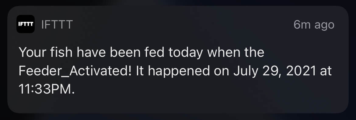
Another cool feature I have is that when the feeder automatically feeds using the set time, I get a push notification on my phone saying something along the lines of "Your fish have been fed on this day at this time." This is more of a quality-of-like improvement than it is a functional one because now, I'll know that the fish have been fed at the exact set time everyday.
Parts List
Below, I have listed every single part I used to make my final project. I included parts that were in the kit as well as parts I either 3D printed or purchased seperately.
From the Kit:
» 1x Small Breadboard
» 1x ESP32 Huzzah
» 1x L9110, H Bridge Power Driver
» 1x N20 DC Gear Motor
» 1x Pushbutton
» 2x 100 Ohm Resistors
» 1x Red LED
» 1x Green LED
» 3x Small M3 Screws
» 3x M3 Nuts
» 1x M3 Washer
» Various Length 26AWG Solidcore Wire
Not From the Kit:
» 1x 3D Printed Electronics Enclosure
» 1x 3D Printed Electronics Enclosure Lid
» 1x 3D Printed Fish Feeder
» 1x 3D Printed Fish Feeder Screw
» 1x Plastic Bottle
» 1x Small Parchment Paper Piece
» 4x Male-to-Female Jumper Wires
» 1x Zip Tie
» Hot Glue
» Super Glue
» Electrical Tape
The Design Process
To start off designing the fish feeder, I looked on Thingiverse for other peoples' designs. I found one in particular that I really liked made by Steve5092 that can be seen by clicking here. I liked the design for one main reason: it has a small form-factor. The design is meant to be used with a DC gear motor, which is perfect because that's what I got in the kit.
Instead of having a rotating drum that acts as a food holder, like I inititally planned on making, this design used a stationary upside-down water bottle as the food holder. With gravity, the food falls onto the screw and then gets pushed when the DC motor is turned on. This also allows storing a good amount of food in the bottle and as long as the other end is covered, the food won't go bad fast.
Unfortunately, the main problem I ran into was that my motor didn't fit in the motor slot. Also, because the screw was so small, it didn't print very well on my 3D printer. I tried to edit original feeder design, but I figured that it would be best to start from scratch with inspiration from this design.
Designing the Fish Feeder
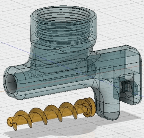
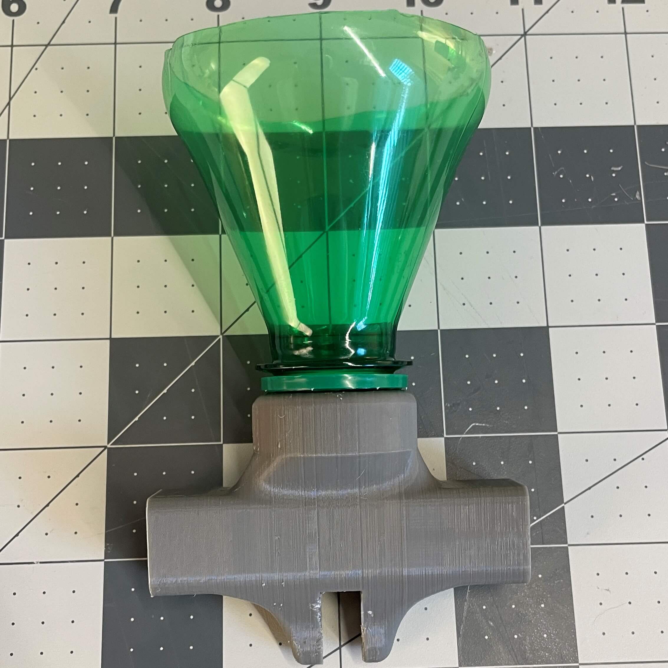
The embedded model viewers below display my final fish feeder model. In the first model viewer, I made the feeder have a translucent appearance to show how the screw fits in the feeder body. The second embedded viewer shows the feeder and screw with their generic grey colors (roughly the same color I 3D printed them in).
I made two main changes to the Thingiverse feeder design to better suit my needs.
One change I made was making the whole feeder larger than it was before. This served two purposes: allowed for a larger screw and better printing easability. In the process, I increased the total screw diameter from 10mm to 16mm. I watched this video by Product Design Online on YouTube for help on making screws on Fusion 360. My screw's inner tube diameter is 10mm, so the threads reach an extra 3mm out, which allows for more food to fit in between the threads. I also increased the thread revolution count from 5 to 10. This allows the food to flow at faster rate because more threads can push more food than less threads can. I also added a little handle part to the end of the screw, so I can easily take it off if needed.
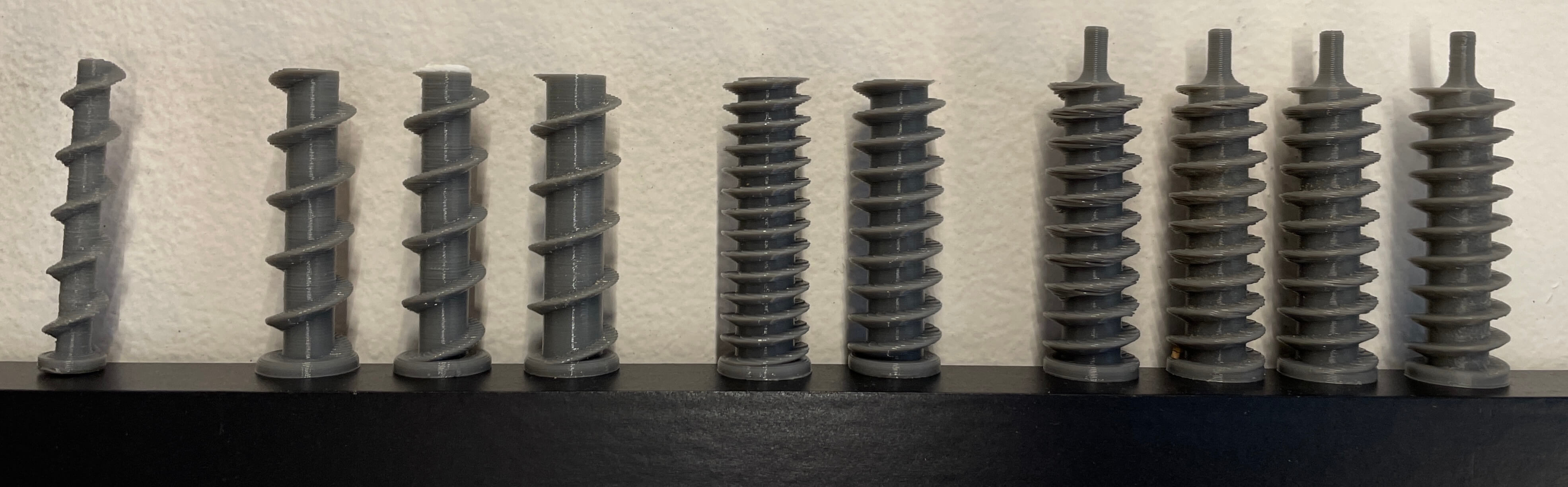
Creating a suitable screw was a bit of a process. The first image below shows all my screw prototypes. The one on the far left is the original one from the Thingiverse design. The next set of three was for experimenting with a different inner tube thickness and screw head thickness. I learned that the larger the variance of thickness between the screw head and the screw threads, the less efficiently the fish food travels through the tube. The next set of two is for experimenting with different revolution counts. I first increased the revolution count to 15, but that made it so the threads were too close together causing the food to get stuck. I dialed it back to 10 revolutions and found that 10 was the perfect amount. The last set of 4 is just experimenting with different layer heights. My final screw uses a 0.1mm layer height, as seen on the far right.
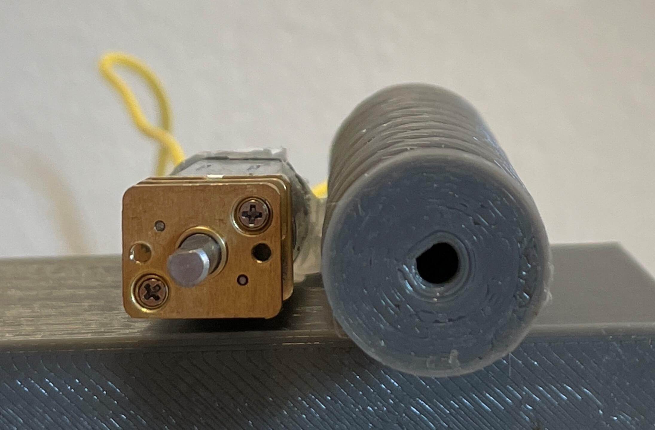
The second image below shows how the DC motor connects to the screw. The DC motor shaft is notched, so one side of the cylindrical shaft is flat. I measured the shaft dimensions and created a hole equal in proportion to the motor shaft but a bit larger to accomodate for the extruded filament thickness. Essentially, it just connects together using friction. This is a good thing because it means I can easily swap out the screw to a different screw if I ever have to. It also means I can easily do maintanence on the feeder if it ever gets jammed.
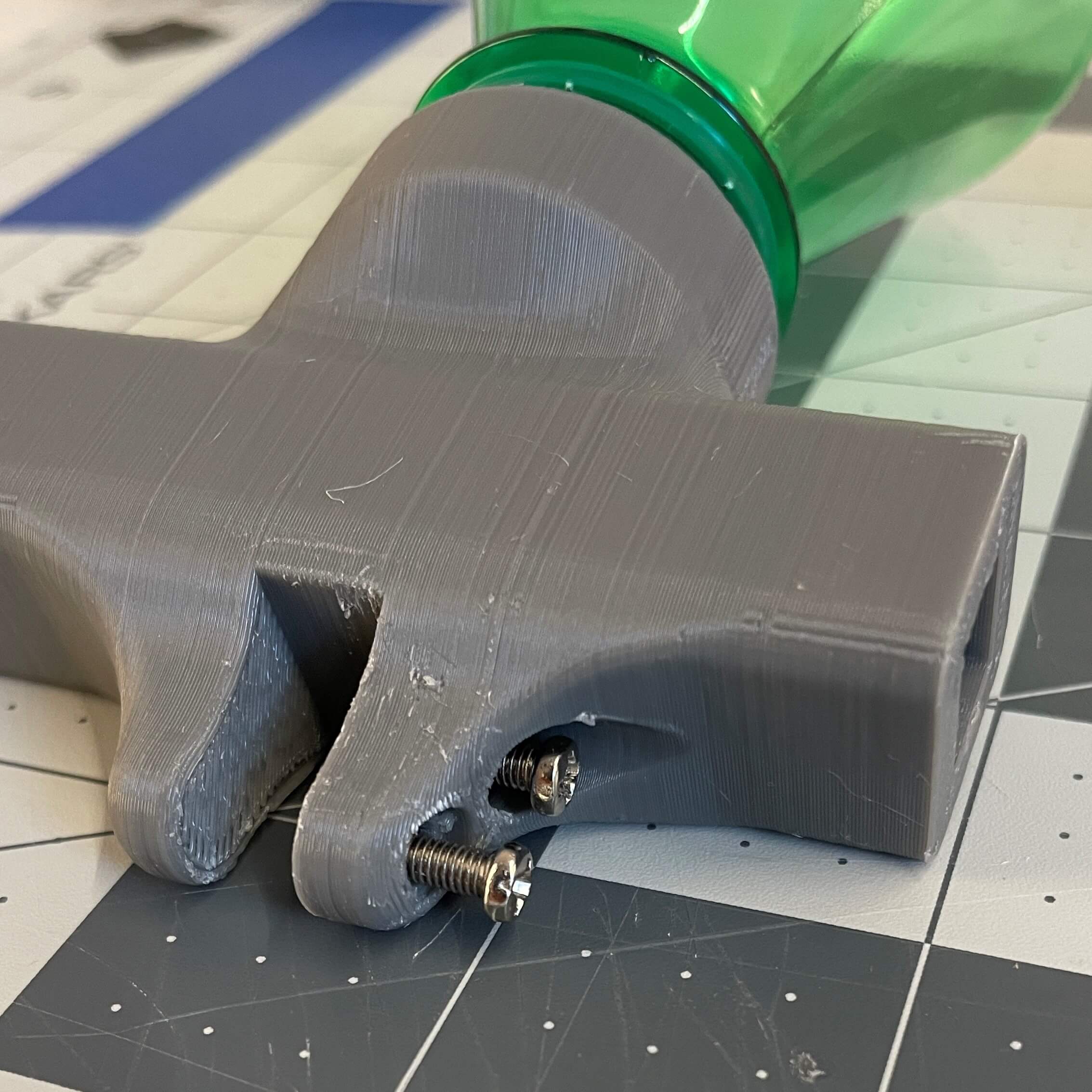
The other main change I made was centering the mounting mechanism. I changed it because it flowed with the whole symmetric design I was going for. On the mount part, I also changed the orientation of the screw holes from horizontal to vertical. The side profile of my mount can be seen in the image to the right.
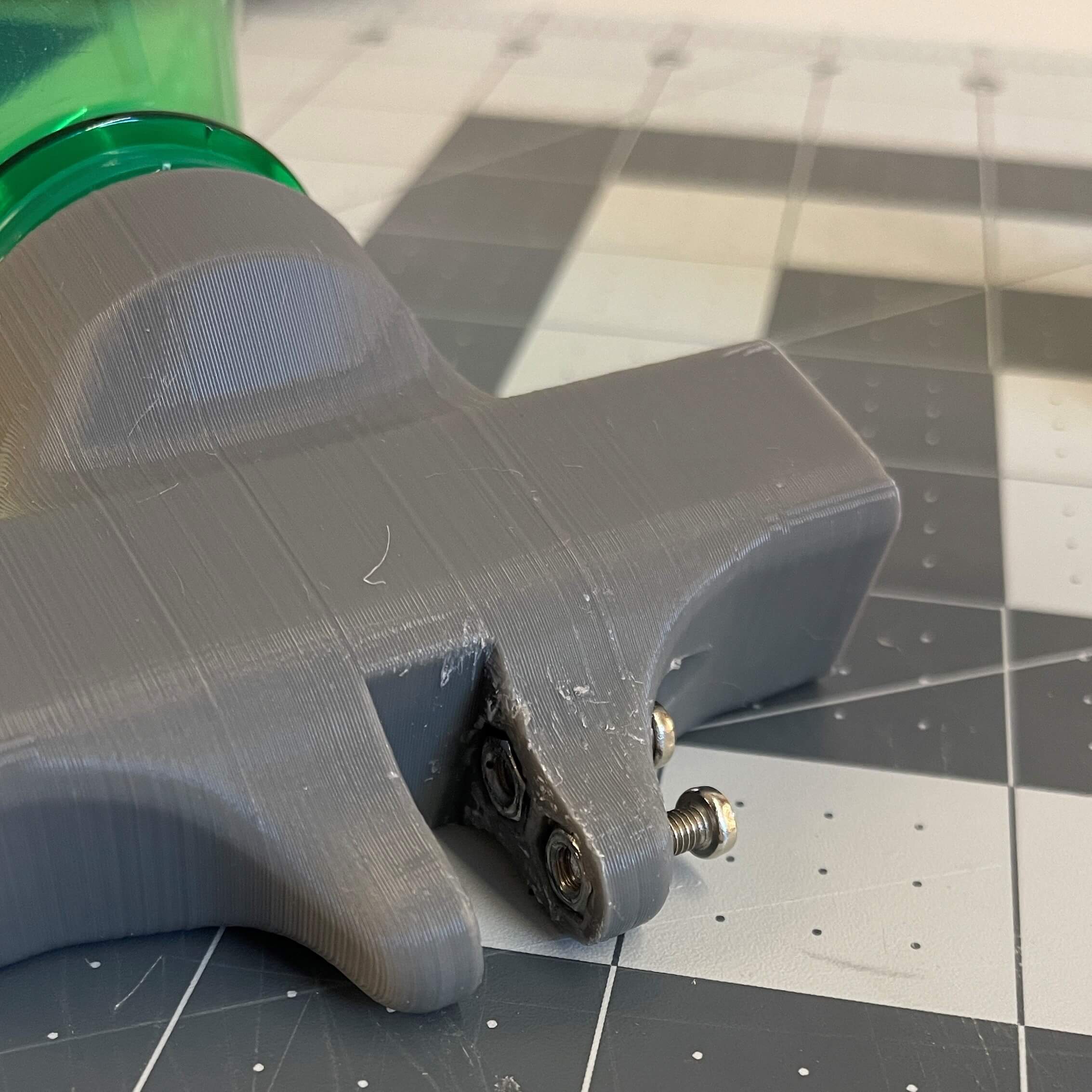
The images below show a close-up of the mount. I super-glued two M3 nuts into the M3 nut sockets so they don't fall out. Two M3 screws can then be screwed in from the right-hand side to create a clamp around the fish tank glass.
Designing the Electronics Box
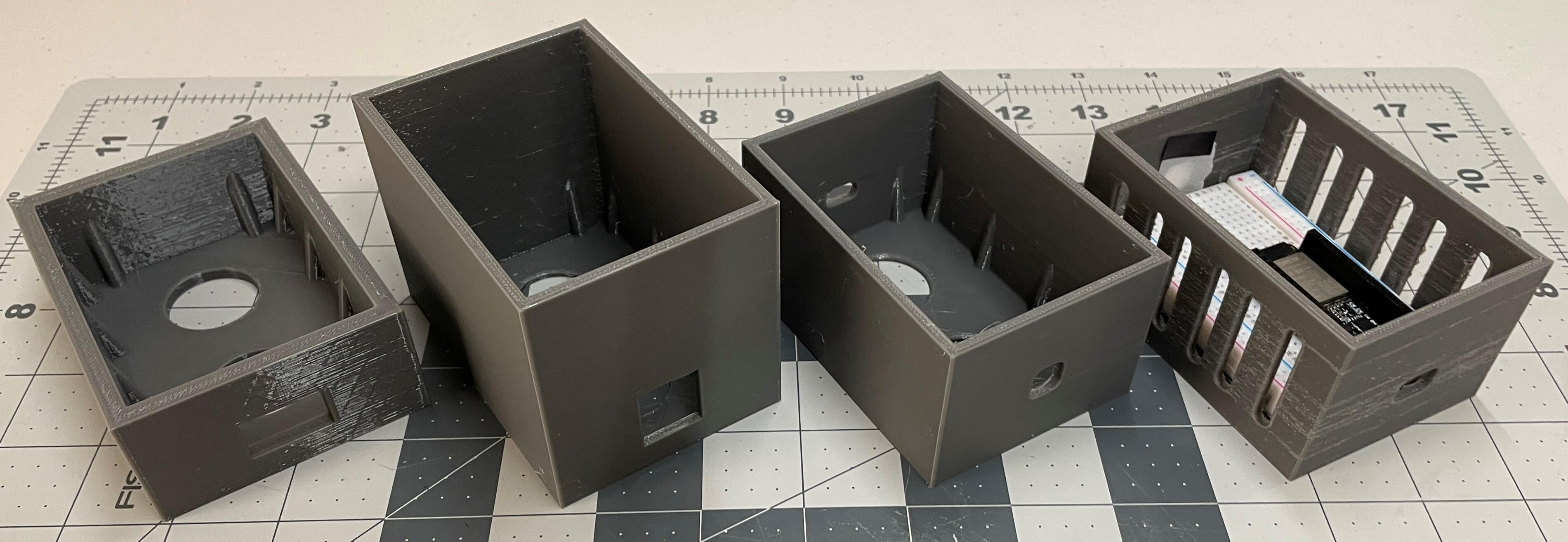
The next step was the create an enclosure for the main electronics (the Huzzah, motor driver, wires, etc). I made a seperate box for the electronics because I didn't want the feeder itself to be bulky, so this was really the only option. The image below shows the three prototype and final enclosures I made.
You can see one of the key design features I implemented in the electronics box below: the extrusions to hold the breadboard in place. I made tiny angled extrusions along the bottom of the walls in the box to act as friction points that hold the breadboard in place. I didn't want to use hardware to physically mount the breadboard in place, so this is a pretty neat solution.
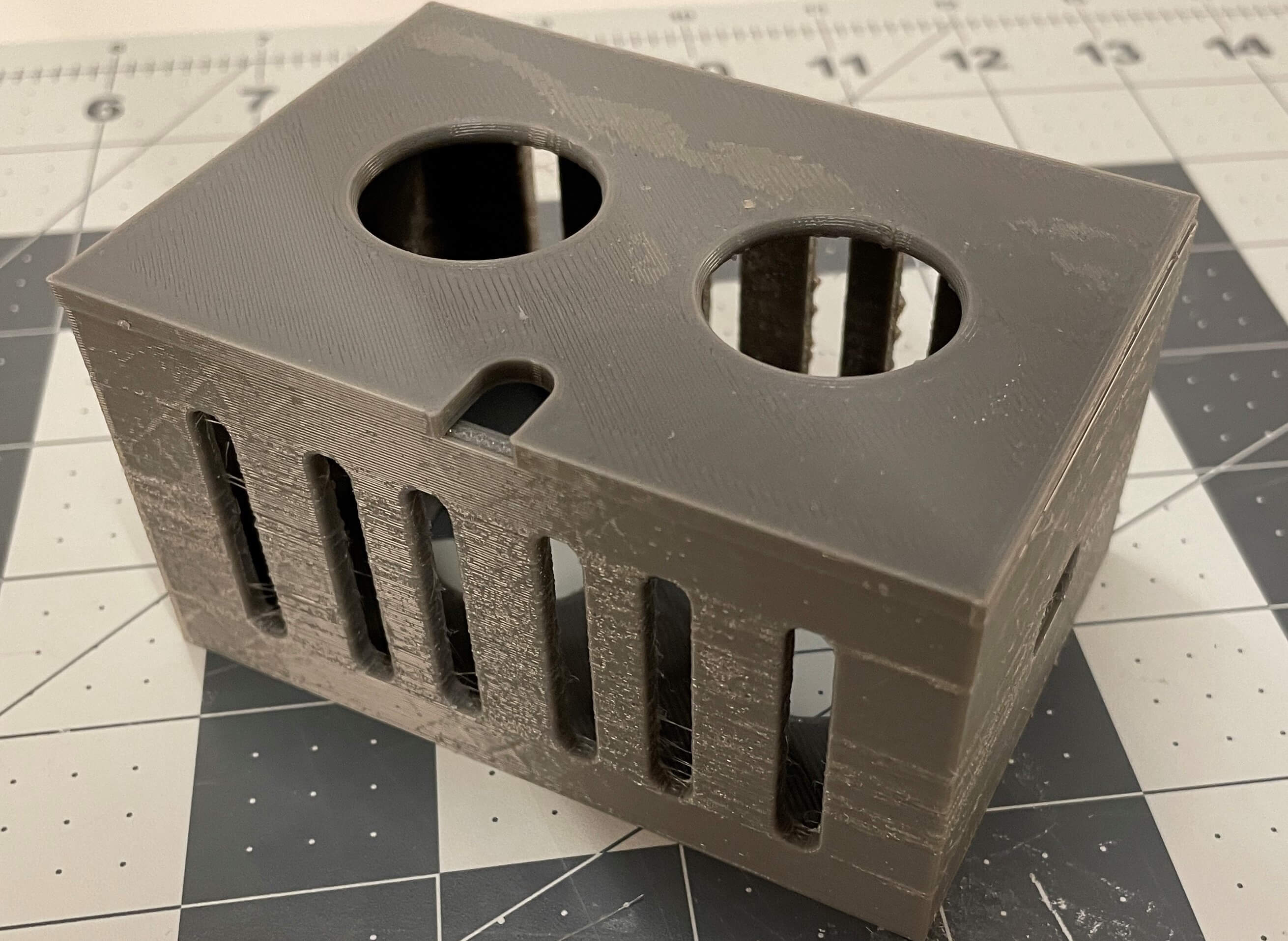
I made cutouts in the walls of the enclosure where the LEDs were going to be, where the Huzzah power cable was going to come through, and on the lid where the motor wires go out of the enclosure. I also made long cutouts on the side walls of the enclosure to give it more of an open look than the previous closed box. In addition to those cutouts, I made circular holes in the bottom of the box and on the lid. The ones on the bottom are for using with my fingers to help orient the breadboard in the correct position and the ones on the lid are for acting as a handle.
On the inside of the LED cutout, I attached a small piece of parchment paper to act as a diffuser when looking through the other side.
One thing to note is that I found the proper box height and cutout positions by doing many tests with the breadboard inside and all wires plugged in. I found that this height of about 50mm with the lid on was perfect for all the electronics I needed.
To the right is the model viewer for the electronics box and lid. This is where the corner extrusion bits are easily visible. I made the holes on the box exactly where they need to be in relation to the breadboard. I also made the hole on the lid for the wires right in the middle, so the wires from the motor driver can go straight up from the box along the side of the fish tank. Also on the lid, I made four tiny sqaure extrusions in all corners to stop the lid from sliding off. The lid stays on without anything else. I was thinking about making a hinge for the lid, but I decided that this was more simple than a hinge mechanism.
Also, one thing I should mention is that I didn't go in this exact order of desigining, wiring, programming, etc when I actually made my feeder. I did all of them together and built on ideas off eachother. For example, the LED hole is only there because I measured the exact spot of the LEDs on the breadboard. And I only have LEDs to begin with because when I was coding for the feeder, I thought making a status indicator would be useful.
That's it for the design process. All of my 3D designs are downloadable by clicking the blue "Open in Fusion 360" button in the bottom right-hand side of the model viewers. Next, I talk about the wiring process.
The Wiring Process
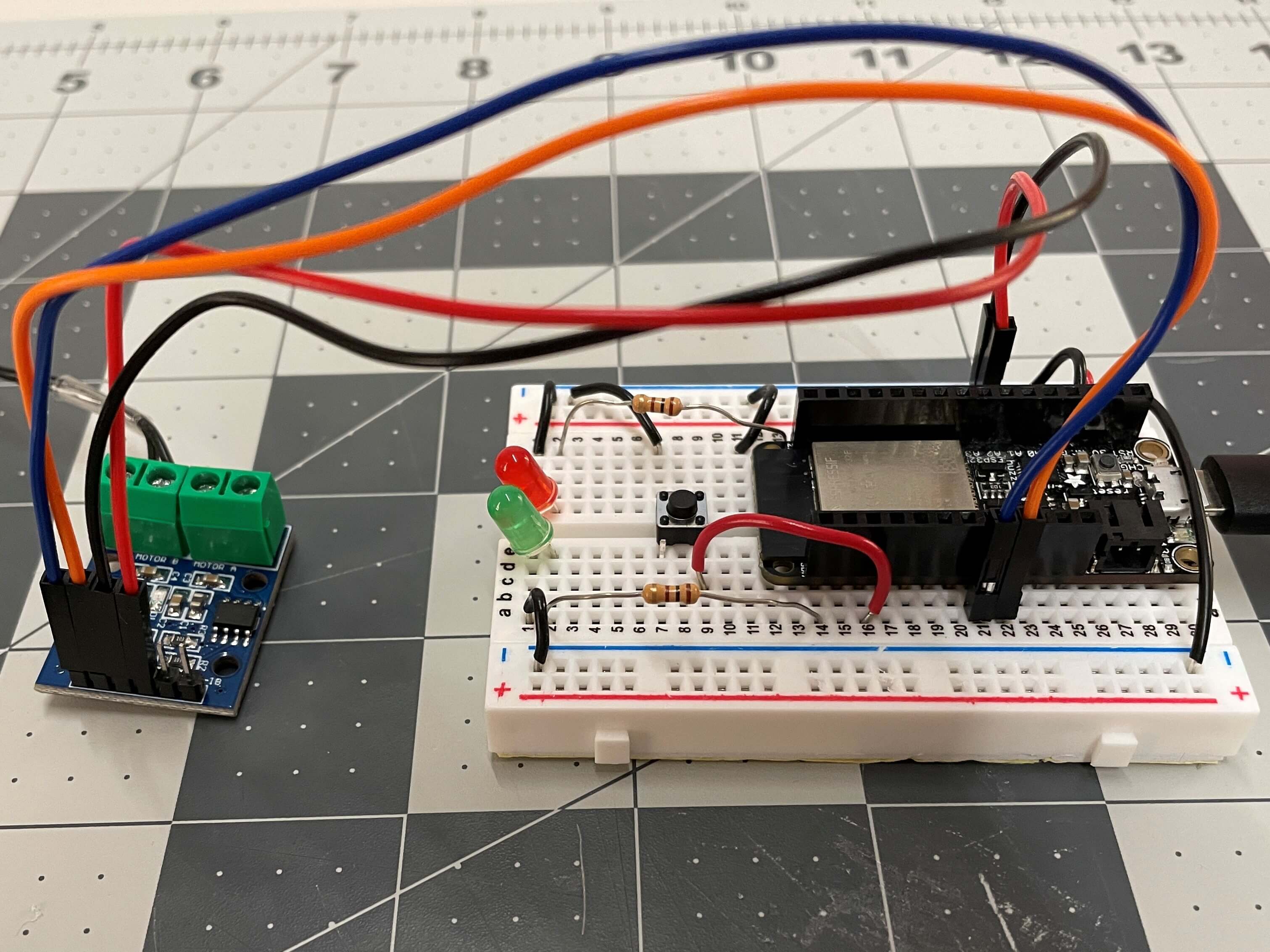
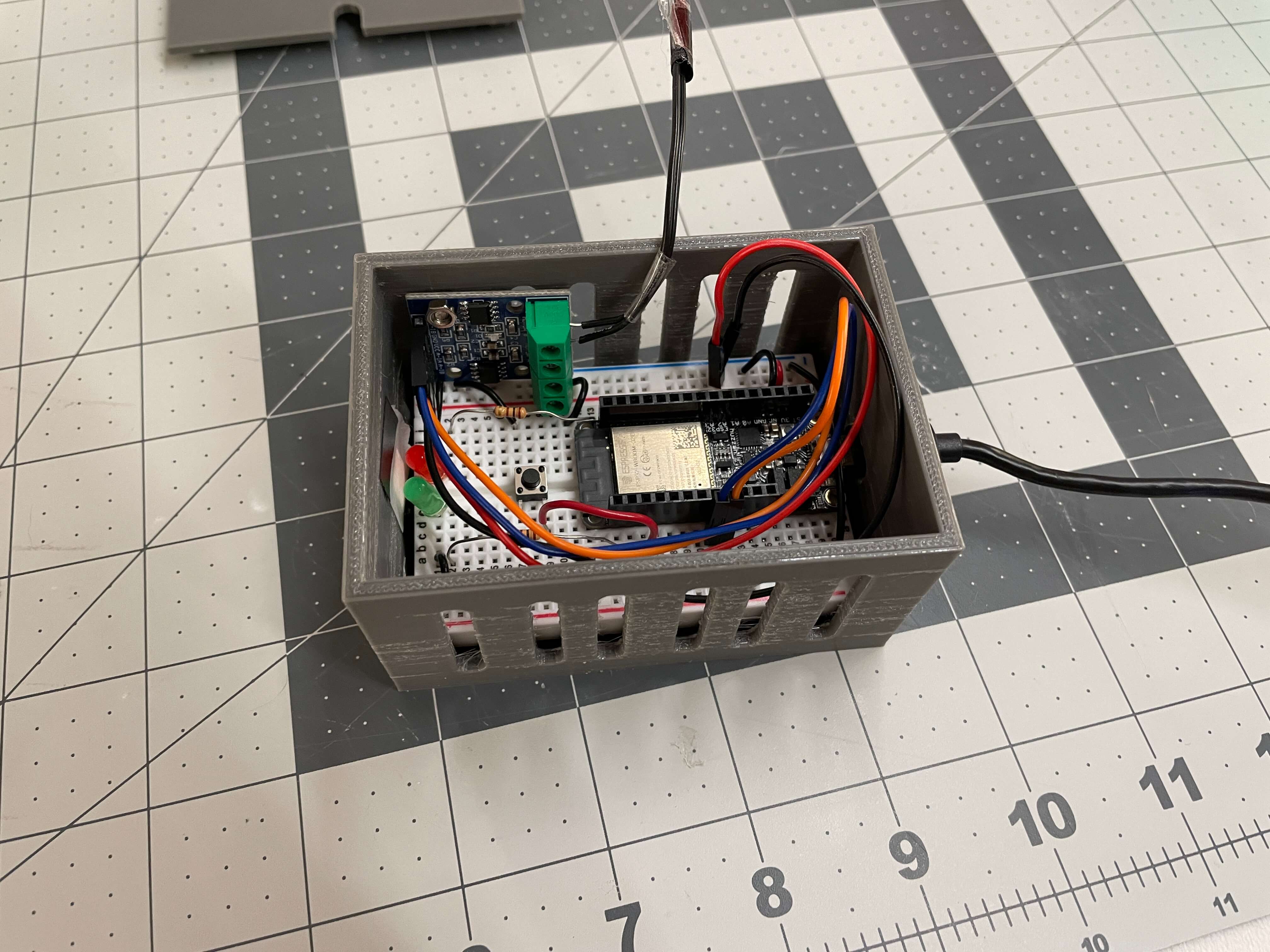
I kept this wiring process section relatively short because the bulk of the features on the circuit are talked about the programming process section. The three pictures below show the circuit from various angles.
Just for a quick summary of the electronics, four wires connect to the motor driver that then has two black wires connecting to the DC motor; the red and green LEDs are status indicators of the feeder where red means "on but not active" and green means "on and active"; and the pushbutton is for manual control, so I can just press that button when I'm next to the feeder to feed the fish instead of going onto the web interface and clicking "On."
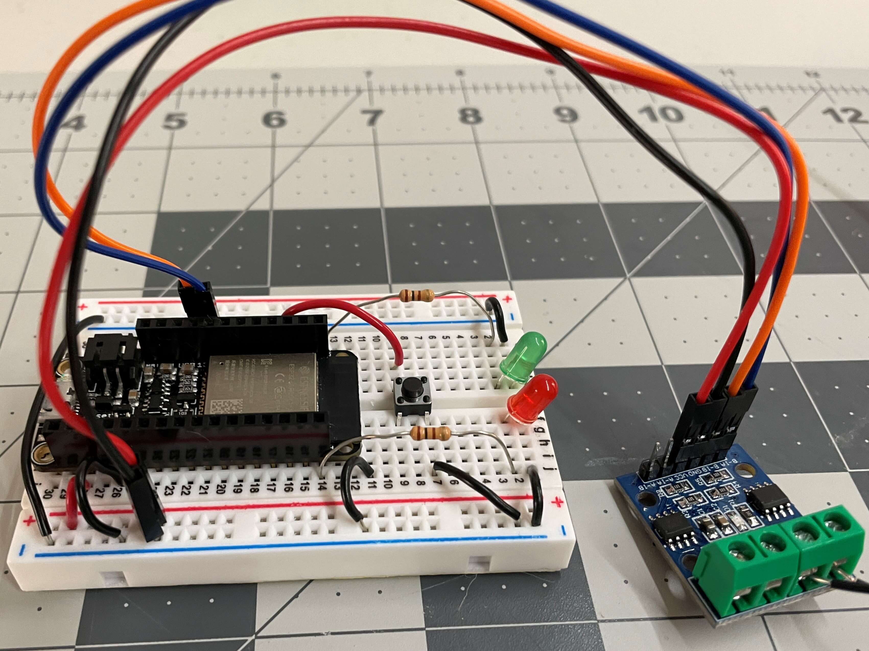
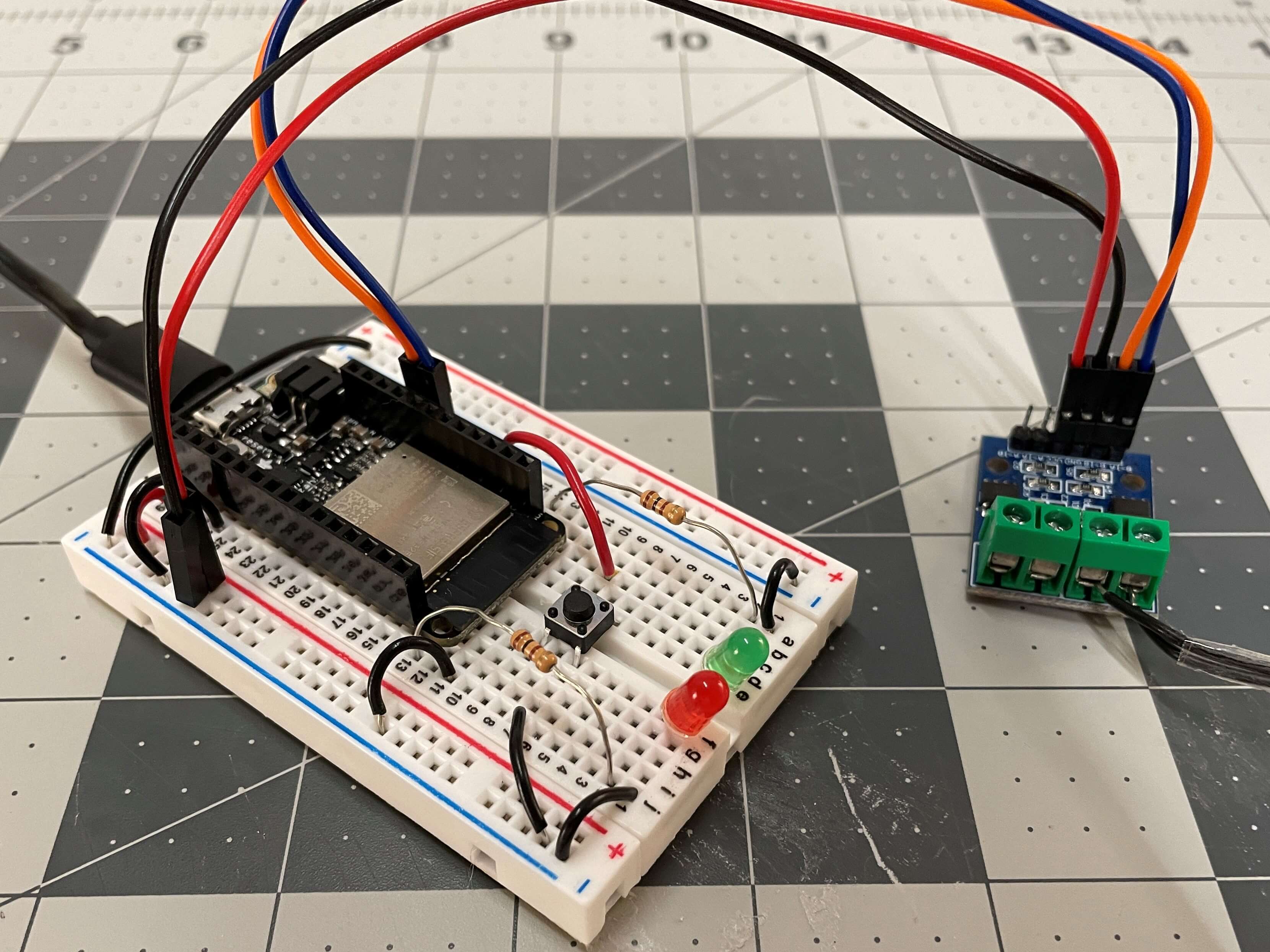
Starting with the motor driver, the orange and blue jumper wires connect pins 13 and 12 on the Huzzah to pins B-1B and B-1A respectively. The red and black jumper wires supply 3V and ground connections to the motor driver pins VCC and GND respectively.
For the LEDs, one 100 Ohm resistors connects the red LED to pin 21 on the Huzzah, and another 100 Ohm resistor connects the green LED to pin 23 on the Huzzah.
For the button, One end of the button connects to pin 14 on the Huzzah and the other connects to ground. Because I am using the built-in pullup resistors, I am not using a resistor for the button.
Lastly, there are two black wires going from the "MOTOR B" connectors on the motor driver to the pins on the DC motor.
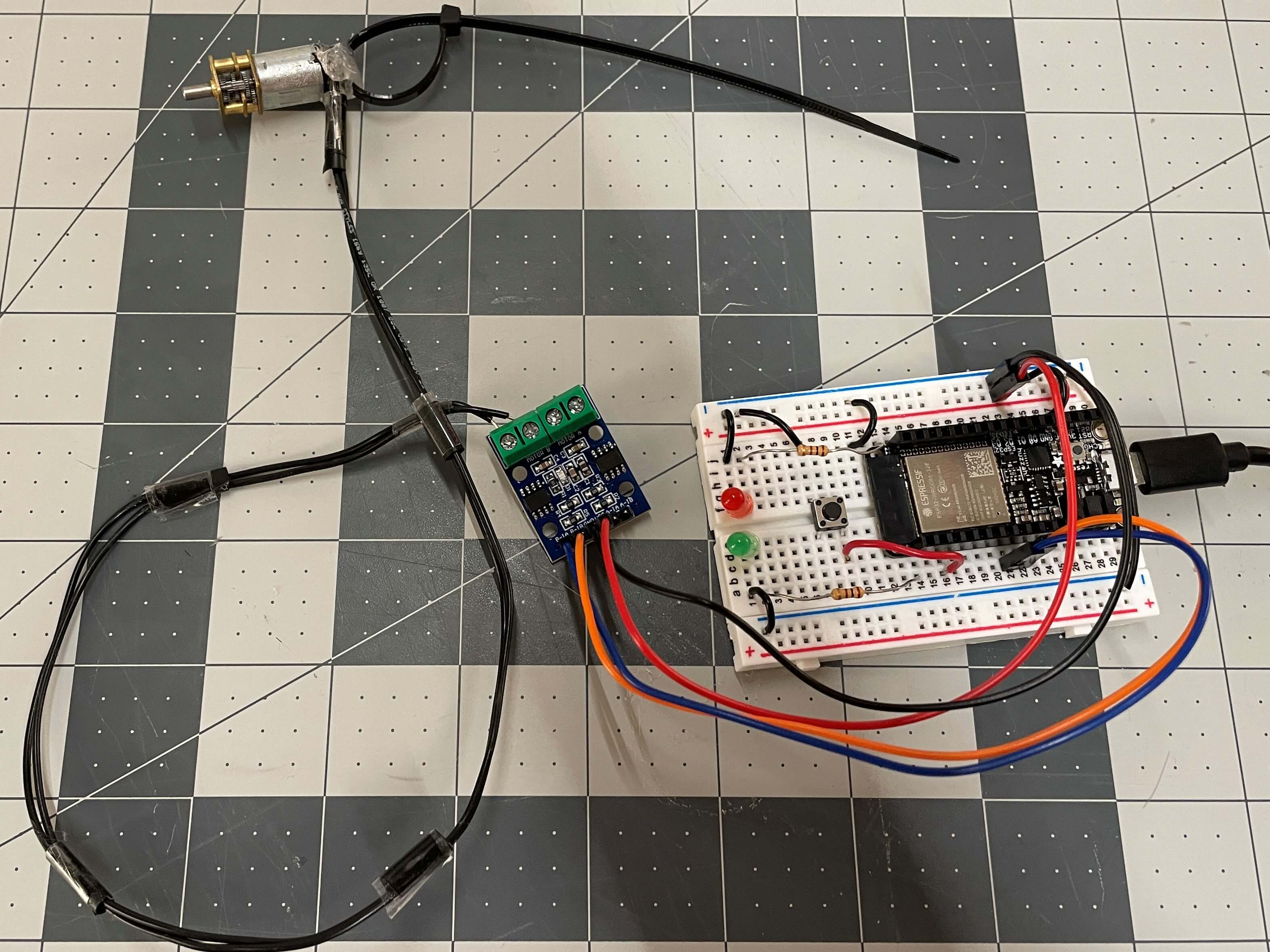
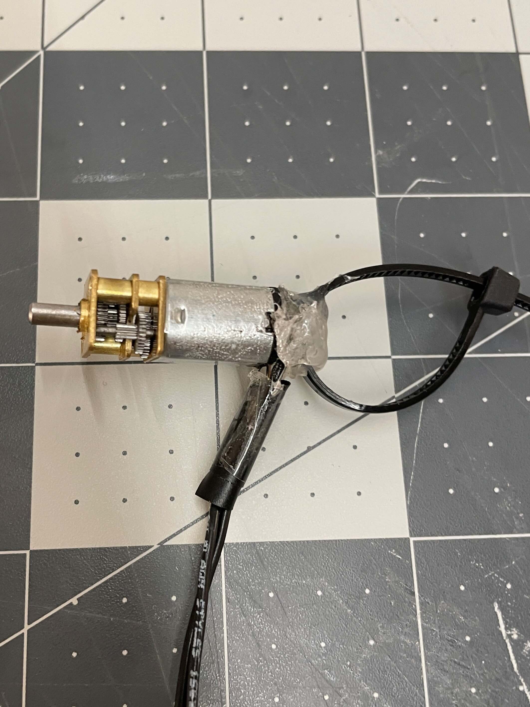
The picture above shows the full circuit and to the right shows a close-up on the motor.
I did a few modifications to the motor. First, I soldered long black wires, replacing the short, yellow ones, so that they are long enough to reach the electronics box on the table from the feeder on the tank and stay relatively hidden against the black back drop of the fish tank.
I then used hot glue to cover the connections and attach a black zip tie to the motor. The glue serves as protection agasint shorting the circuit and the zip tie is for easily pulling the motor out of the socket.
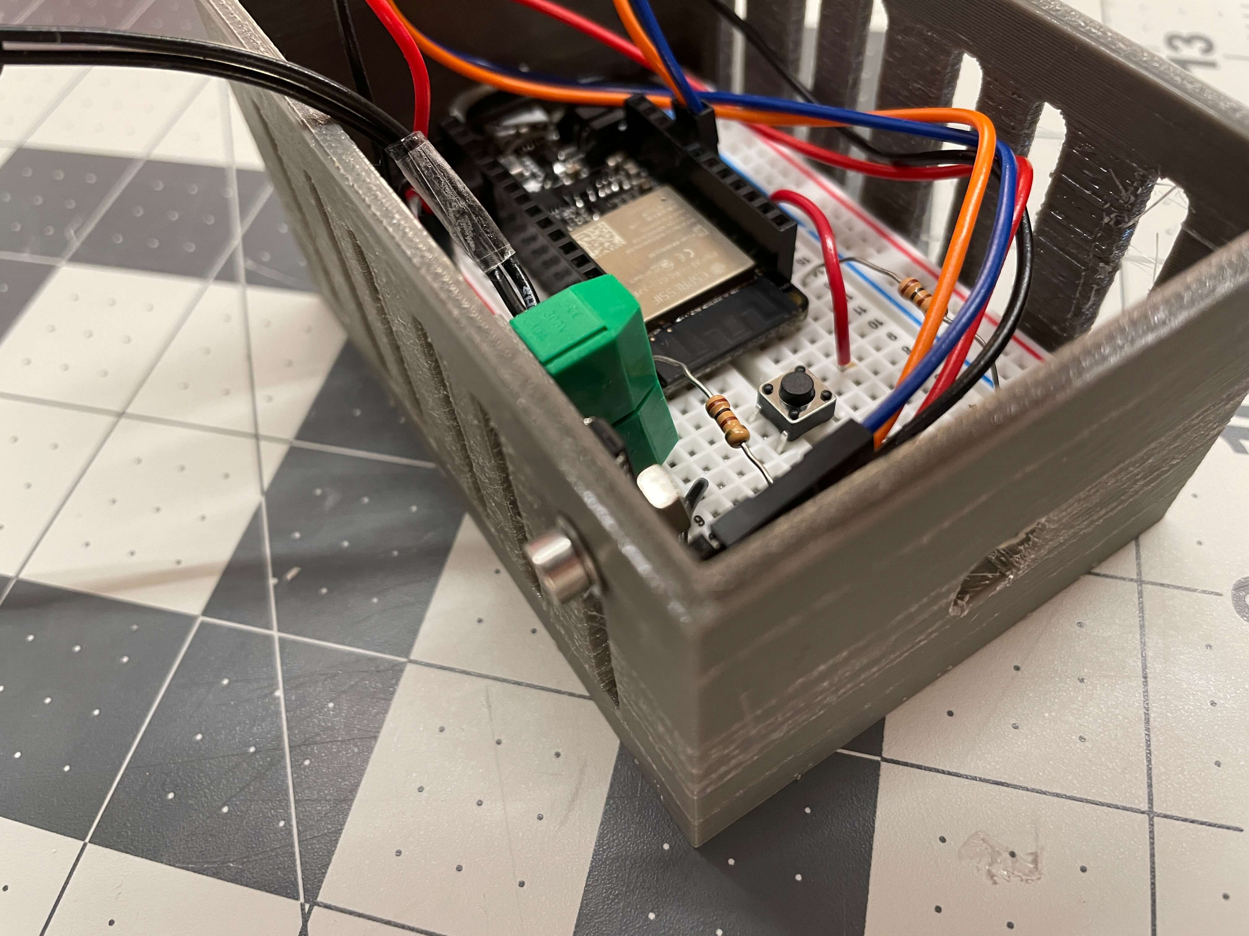
The images below show what the breadboard circuit looks like when inside the electrical box. It's a bit cramped, but it still fits everything perfectly.
One thing I did to prevent the wires from ripping out of the board if I dropped the electrical box was screwing one corner of the motor driver to the side walls. The side holes were a completely a design choice that ended up being really helpful because of that screw. The picture to the bottom right shows the motor driver attached to one of the sides using the small M3 screw, an M3 washer, and an M3 nut. Screwing the driver in ensures that if the electrical box (or the fish feeder) ever drops, then the wires don't take out the whole thing. In this case, the two black wires may come out of the driver sockets, but they won't pull the driver and other wires out with them.
The Programming Process
This section is for the coding part of my fish feeder. Because I have already talked about most of the code in my assignment 11 webpage, I'll breifly go over the different parts of the code.
Below, I have embeded the full code for my final project. Further below the embed, I talk about parts of the code.
Just a quick note, in the code itself, I wrote a lot of pseudo code to explain what each line of code means.
Full Arduino Code
Arduino Code Overview
Now, I'll talk about the code in parts.
Starting off the code with the global section, lines 1-6 are for including the necessary libraries.
// Libraries
#include <FirebaseESP32.h>          // Firebase library
#include <WiFi.h>                   // ESP32 WiFi library
#include "time.h"                   // Arduino's time library. Needed for NTP client
#include <Arduino.h>                // Needed for the AnotherIFTTTWebhook library
#include "AnotherIFTTTWebhook.h"    // IFTTT Arduino library made by Siytek
Lines 8-19 are for defining Firebase, WiFi, and IFTTT info. These will be referenced to later when the code calls for their respective functions. I left mine blank for privacy reasons, but the actual code has all the real info.
// Firebase hosting link and authentication key
#define FIREBASE_HOST ""      // The project name address from firebase ID
#define FIREBASE_AUTH ""      // The secret key generated from firebase
FirebaseData firebaseData;

// Wifi SSID and password
#define WIFI_SSID ""
#define WIFI_PASSWORD ""

// IFTTT Webhooks event name and key
#define IFTTT_Key ""                      // Secret key given by IFTTT
#define IFTTT_Event "Feeder_Activated"    // Name of the event I set on IFTTT
Lines 21-28 are for defining data recieved from Firebase as string data types and defining variables for the NTP client. I talk more on the Firebase stuff later. For the NTP client, I just followed this NTP client guide by Random Nerd Tutorials. The tutorial is really comprehensive and easy to understand. The changes I made were setting the server to the U.S. server and changing to offset to -18000 seconds (-5 hours) because I live in the Central Time Zone (CST), which is 5 hours behind Greenwich Mean Time (GMT). Also, if needed, I can change the daylight offset to 3600 seconds (1 hour) to enable a time offset for daylight savings.
// Data recieved from Firebase
String feedingTimeString = "";      // Daily feeding time received as string data from firebase
String feederStatusString = "";     // Feeder status received as string data from firebase

// NTP server stuff for time
const char* ntpServer = "us.pool.ntp.org";
const long  gmtOffset_sec = -18000;
const int   daylightOffset_sec = 0;
Lines 30-39 are for defining the motor, LED, and button pins to their respective names I created. I could've used the #define function for the pins, but I prefer to create const int variables instead to differenciate between defining long variables and pins.
// Defining DC motor pins
const int motorSpd = 13;
const int motorDir = 12;

// Defining LED motor pins
const int greenLED = 23;
const int redLED = 21;

// Defining physical button pin (button on breadboard)
const int physicalButton = 14;
Lines 41-46 are for defining cycle variables by set times. These variables will then be used later when their respective functions (One Cycle, Two Cycles, etc) are called. This is just to make editing the set cycle feeding times easy if I ever need to.
// Creating time delays for each feeding cycle and daily feeding time
const int oneCycleTime = 1500;
const int twoCycleTime = 2000;
const int threeCycleTime = 2500;
const int dailyFeedingCycleTime = oneCycleTime;
const int dailyFeedingCyleTimeDelay = 60000 - dailyFeedingCycleTime;
Finally, starting with line 49, the setup function begins. Lines 50-61 are for starting a serial monitor, which is used for debugging, and initializing the WiFi connection between the Huzzah and my home WiFi.
void setup() {
  Serial.begin(115200);
  delay(1000);

  // Connect to wifi
  WiFi.begin(WIFI_SSID, WIFI_PASSWORD);

  Serial.print("Connecting to ");
  Serial.print(WIFI_SSID);
  while (WiFi.status() != WL_CONNECTED) {
    Serial.print(".");
    delay(500);
  }
Lines 63-71 are for connecting the Huzzah to Google Firebase. This is where I set the "FEEDER STATUS" as "OFF". The "FEEDER STATUS" is one piece of data that is recieved by the Huzzah from Firebase. I talk about this later, but in summary, this changes to "ON" if the feeder is manually turned on, and changes to "ONE CYCLE," "TWO CYCLES," or "THREE CYCLES" when the respective cycle is activated on the web interface.
Serial.println();
Serial.print("Connected to ");
Serial.println(WIFI_SSID);
Serial.print("IP Address is : ");
Serial.println(WiFi.localIP());
Firebase.begin(FIREBASE_HOST, FIREBASE_AUTH);         // Connect to firebase
Firebase.reconnectWiFi(true);
Firebase.set(firebaseData, "/FEEDER STATUS", "OFF");  // Set initial status to "OFF"
Lines 73-74 are for initializing the NTP server connection. This is how the Huzzah recieves the current time value. The line of code uses the gmtOffset_sec, daylightOffset_sec, and ntpServer variables I globally defined above the setup function.
// Initialize NTP server connection to get the current time
configTime(gmtOffset_sec, daylightOffset_sec, ntpServer);
Lines 76-85 are for defining min modes for the motor, LED, and pushbutton pins. To signify the use of a pullup resistor, I defined the pinMode for the pushbutton as INPUT_PULLUP.
// Motor pin modes
pinMode(motorDir, OUTPUT);     // Connects to B-1B on motor driver. Controls motor speed
pinMode(motorSpd, OUTPUT);     // Connects to B-1A on motor driver. Controls motor direction

// LED pin modes
pinMode(redLED, OUTPUT);       // Connects to pin 23 on the Huzzah ESP32
pinMode(greenLED, OUTPUT);     // Connects to pin 21 on the Huzzah ESP32

// Pin mode for physical button
pinMode(physicalButton, INPUT_PULLUP);  // Connects to pin 32 on the Huzzah ESP32
To end off the setup of the code, I defined the status of the motor and LEDs. I set the red LED to on and the green to off. Also, I have the motor starting in a counter-clockwise direction because that's the way the screw needs to spin for the food to come out the front end. I also set the speed to 0 because I don't want it spinning right when I power the Huzzah.
// setting starting motor and LED statuses
  digitalWrite(redLED, HIGH);
  digitalWrite(greenLED, LOW);
  digitalWrite(motorDir, LOW);
  digitalWrite(motorSpd, LOW);
}
The first set of code in the loop function is for creating the Firebase inputs. Lines 96-105 is where the data recieved from Firebase is actively being turned into string data, which the Huzzah can actually use. The two data inputs I made are "FEEDING TIME" and "FEEDER STATUS." As the name implies, "FEEDING TIME" is for recieving the set feeding time, and the "FEEDER STATUS" shows whether the feeder is actively feeding or not.
The image below shows what the data points look like my Firebase realtime database.
This data is changed using the web interface, which I talk about later, and is then recieved by the Huzzah, sort of like a chain of command. The chain starts from the web interface, then goes to Firebase, and finally the data is outputted to the Huzzah.
void loop() {

  /*
     Creating firebase inputs.
  */
  Firebase.get(firebaseData, "/FEEDING TIME");     // Get feeding time input from firebase
  feedingTimeString = firebaseData.stringData();   // Change to e.g. intData() or boolData()
  //Serial.println(feedingTimeString);             // For debugging

  Firebase.get(firebaseData, "/FEEDER STATUS");    // Get feeder status input from firebase
  feederStatusString = firebaseData.stringData();
  //Serial.println(feederStatusString);
Lines 108-121 are for recieving an active time from the NTP client. I first created a char data type that stores the current time. Then, I use the strftime function with the %R specifier to format time recieved from the client into military time using hr:min format that then constatly updates the currentTime variable. I wanted to use military time to set the time to make the web interface simple. Also, I have other timers for my fish tank that use military time, so I can keep them all in sync. Information on the strftime function and specifiers can be found by clicking here.
/*
    This section is for printing and defining varialbes to time recieved from NTP server.
*/
struct tm timeinfo;
if (!getLocalTime(&timeinfo)) {
Serial.println("Failed to obtain time");
return;
}

//Serial.println("Time in HR:MIN");
char currentTime [6];                         // Saving hour variable as char data type
strftime(currentTime, 6, "%R", &timeinfo);    // Strifetime() command for formatting time
Serial.println(currentTime);
Serial.println();
Finally, we've reached the code for the actual feeding functions. To kick things off, lines 124-145 is where the daily feeding cycle code is. Note that within the if() statement, the variable feedingTimeString is being used. The if() statement basically says "if the time set on the web interface is equal to the current time recieved from the NTP client, run the code below." The code below is just turning the DC motor on for 1 second, which is the length of one cycle, and then turn off for 59 seconds, which is the delay I set. The reason for this is because the time recieved from the interface and the current time are equal for 1 whole minute, meaning that the if() statement activates for the period of the whole minute. With a delay of 59 seconds, the if() statement is only able to run once, thus solving the issue.
Within the if() statement, there's also line 130, which calls for the function sendIFTTTData();. This is calling for the void sendIFTTTData function I created below the void loop function that, when activated, triggers the IFTTT event. I haven't talked about IFTTT yet, which I will do later, but in a nutshell, when the event is triggered, a notification pushed out to my phone saying something along the lines of "Your fish have been fed! This happened on *whatever time*." I'll explain more thoroughly what IFTTT is when we get to that void function.
/*
    This section is for recieving the input data from firebase
    and sending outputs to the motor and the status LEDs.
*/
  // Daily set feeding time
  if (feedingTimeString == currentTime) {   // Compare current time to web interface input
    sendIFTTTData();                        // Executes sendData function
    digitalWrite(motorSpd, HIGH);           // Motor turns on at max speed
    digitalWrite(motorDir, LOW);            // Motor turns in a counter-clockwise direction
    digitalWrite(redLED, LOW);              // The red LED turns off and green turns on
    digitalWrite(greenLED, HIGH);

    delay(dailyFeedingCycleTime);           // Active feeding time set as delay

    Serial.println("Motor Turned OFF");
    digitalWrite(motorSpd, LOW);
    digitalWrite(motorDir, LOW);
    digitalWrite(redLED, HIGH);
    digitalWrite(greenLED, LOW);

    delay(dailyFeedingCyleTimeDelay);       // Delay after feeding
  }
Lines 147-161 are for manual on and off control. One thing to note though is that variable in the if() statement that is being compared is feederStatusString and not feederTimeString like before, It works pretty similarly to how the daily cycle feeding does, where if the "On" button on the web interface is pressed, the FEEDER STATUS on Firebase gets updated, and then the motor turns off. The motor stays on until the "Off" button is pressed on the interface.
// Manually on mode
  if (feederStatusString == "ON") {
    digitalWrite(motorSpd, HIGH);
    digitalWrite(motorDir, LOW);
    digitalWrite(redLED, LOW);
    digitalWrite(greenLED, HIGH);
  }

  // Manually off mode
  else if (feederStatusString == "OFF") {
    digitalWrite(motorSpd, LOW);
    digitalWrite(motorDir, LOW);
    digitalWrite(redLED, HIGH);
    digitalWrite(greenLED, LOW);
  }
Lines 163-177 are for the "One Cycle" function of the feeder. Again, like the previous if() statement, if this if() statement gets updated to "ONE CYCLE," then the code runs. Because this cycle is timed, I used a Firebase.set command after the cycle that sets the FEEDER STATUS to "OFF" or else, on Firebase, the "FEEDER STATUS" would just show as "ONE CYCLE" forever until another button is pressed.
Also, because the two and three cycle lines of code are the exact same as the once cycle's code with only a difference in delay length, I skip talking about two and three cycles, lies 179-209.
// Manually feed for one cycle
  if (feederStatusString == "ONE CYCLE") {
    digitalWrite(motorSpd, HIGH);
    digitalWrite(motorDir, LOW);
    digitalWrite(redLED, LOW);
    digitalWrite(greenLED, HIGH);

    delay(oneCycleTime);                      // Feeds for set time

    digitalWrite(motorSpd, LOW);
    digitalWrite(motorDir, LOW);
    digitalWrite(redLED, HIGH);
    digitalWrite(greenLED, LOW);
    Firebase.set(firebaseData, "/FEEDER STATUS", "OFF");  // Set feeder status in firebase to "OFF"
  }
The last set of code in the loop function is in lines 211-226. This is for manually controlling the feeder with a pushbutton on the breadboard itself, not on the interface. It works exactly the same as the one cycle one does, in terms of functionality, but the only difference is that I use a digitalRead function to detect the status of the button. If it detects as LOW, then one cycle of feeding occurs, as it uses the same delay as the one cycle is.
// Using the physical button on the circuit
  if (digitalRead (physicalButton) == LOW) {
    Serial.print ("Button On");
    digitalWrite(motorSpd, HIGH);
    digitalWrite(motorDir, LOW);
    digitalWrite(redLED, LOW);
    digitalWrite(greenLED, HIGH);

    delay(oneCycleTime);                       // Feeds for set time

    digitalWrite(motorSpd, LOW);
    digitalWrite(motorDir, LOW);
    digitalWrite(redLED, HIGH);
    digitalWrite(greenLED, LOW);
  }
}
At last, we have reached the end of the code. Lines 228-235 are for sending push notifications to my phone using the app IFTTT, which stands for If This Then That. This is what the second tab, the IFTTT library, is for. To be completely honest, I have no idea what any of the code in the second tab means (because I just downloaded that library from Siytek's GitHub while following hig guide. All I know is that this is the only one I have found to work. Anyway, this is void function is called to when the daily feeding cycle activates, which then triggers an event on IFTTT, and finally sends a push notification to me.
Since I already wrote about my experience with IFTTT on my assignment 11 webpage, I'll briefly go over it below.
void sendIFTTTData() {
  /*
     The one line below is for triggering the Feeder_Activated event on
     IFTTT. Calling to this function means a push notification sends to
     my phone saying something along the lines of "Your fish have been fed."
  */
  send_webhook(IFTTT_Event, IFTTT_Key, "Char 1", "Char 2", "Char 3");
}
Sending Push Notifications Using IFTTT
IFTTT is "is a service that allows a user to program a response to events in the world," as written by Wikipedia. Essentially, you make "if" and "then" statements for virtually anything. For example, if someone rings your doorbell, you can have IFTTT set up to send you a notification on your phone, log it down on a spreadsheet, turn the front lights on, etc.
In my case, I am using "Webhooks" as my "if" statement. Using webhooks is the way to recieve web requests on IFTTT, meaning that's how the Huzzah will be communicating with the IFTTT app.
For my "then" statement, I'm using "Notifications" as the output. This is how IFTTT will respond when a web request is recieved from the Huzzah.
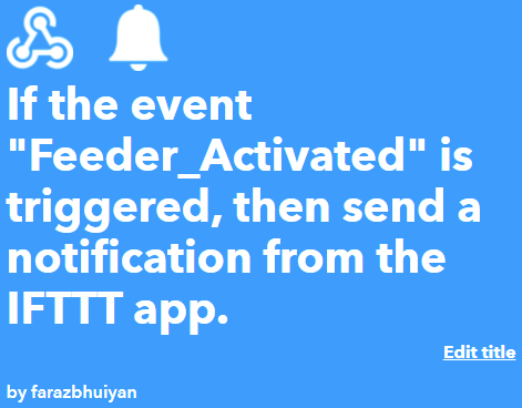
The pictures below show my main Applet screen. An Applet is one whole "if this" event happens "then that" event occurs app. Hence the name Applet. The title of my Applet is the first image below. The second image is of my Applet's "if" and "then" settings page, where I can edit what is the "if" event and what is the "then" result.
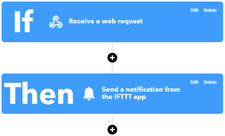
One thing to note is that in the picture above, the black "+" signs are for adding filters to the data and querying subsets of the data. Because I don't have the pro version of IFTTT, I don't have access to that.
Below are images of what I specifically set as the "if" and "then" statements.
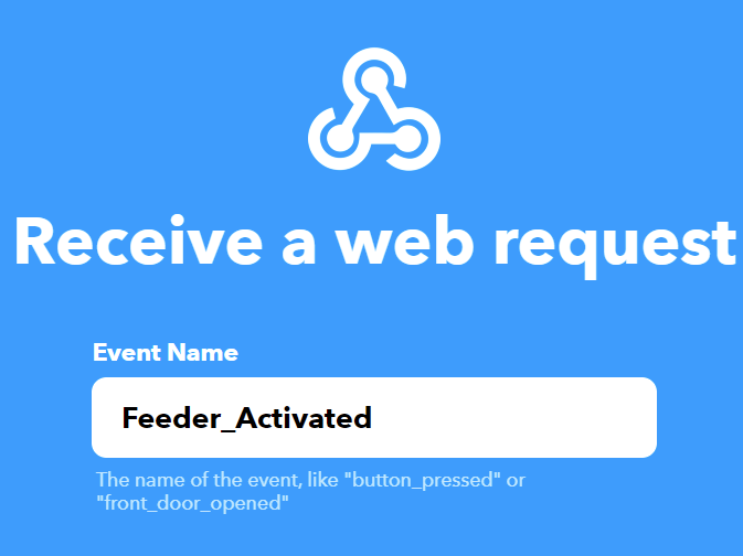
The "if" statement is where I created the event name "Feeder_Activated." I put in this event name in the Arduino code as the IFTTT_Event. This is what triggers when the daily feeding time equals the current time (when the fish feeder automatically runs).
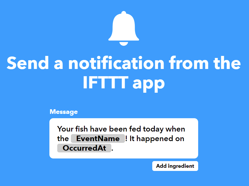
Then, for my "then" statement, I have a notification pushed from the IFTTT app on my phone. The actual messsage can be changed to whatever you want, but I have it set so it tells me the event, "Feeder_Activated," occured and at what time it occured. The time part is just for keeping track of what time I have set, so I don't always have to go back to the interface.
And that's it for setting up an IFTTT Applet. I'd recommend checking out this project guide by Uladzislau Bayouski on setting up Webhooks and Notifications on IFTTT and this guide by Siytek on connecting Arduino to IFTTT.
Creating the Web Interface
In this section, I'll talk about the JavaScript I wrote for the web interface to work. I won't go over the CSS because really any CSS config works as long as you create the right classes. I also used the same bootstrap theme as I have on this website, so I won't go over that either.
Like I did for the programming section, I'll first embed the whole code below and then later talk about certain parts further below.
Web Interface HTML and JS Code
<!DOCTYPE html>
<html lang="en">

<head>
    <meta charset="utf-8">
    <meta http-equiv="X-UA-Compatible" content="IE=edge">
    <meta name="viewport" content="width=device-width, initial-scale=1">

    <title>Faraz's Automatic Fish Feeder Web Interface</title>

    <link href="./css/bootstrap.min.css" rel="stylesheet">
    <link href="./css/custom.css" rel="stylesheet">
</head>

<body>
    <div class="container">
        <div class="row">
            <div class="col-sm-12">
                <div style="text-align: center">
                    <h1><b> Automated Daily Feeding</b><br></h1>
                    <h3>(Use military time in hr:min format. e.g. "09:15" or "15:30")</h3>
                    <input type="text" id="FeederSet">
                    <button onclick="setFeedingTime()">Set Feeding Time</button> <br><br>
                </div>
            </div>
        </div>

        <div class="row">
            <div class="col-sm-12">
                <div style="text-align: center">
                    <h3>Last set feeding time:</h3>
                    <h2 id="lastSetTime">00:00</h2>
                </div>
            </div>
        </div>

        <hr>

        <div class="row">
            <div class="col-sm-12">
                <div style="text-align: center">
                    <h1><b>Manual Control</b></h1>
                    <button class="custombutton" id="OnButton" onclick="OnButton()">On</button>
                    <button class="custombutton" id="OffButton" onclick="OffButton()">Off</button>
                </div>
            </div>
        </div>

        <div class="row">
            <div class="col-sm-12">
                <div style="text-align: center">
                    <button class="custombutton2" id="OneCycle" onclick="OneCycle()">One Cycle</button>
                    <button class="custombutton2" id="TwoCycles" onclick="TwoCycles()">Two Cycles</button>
                    <button class="custombutton2" id="ThreeCycles" onclick="ThreeCycles()">Three Cycles</button>
                </div>
            </div>
        </div><br>

        <hr>

        <div class="row"><br>
            <div class="col-sm-12">
                <img class="img-rounded2 center" src="Shrimp.jpg" style="width:50%" alt="Shrimp"><br>
                <p style="text-align: center"> Feed us! -Shrimp and Shrimpette</p>
            </div>
         </div>
    </div>


<!-- The core Firebase JS SDK is always required and must be listed first -->
<script src="https://www.gstatic.com/firebasejs/7.13.2/firebase-app.js"></script>

<!-- TODO: Add SDKs for Firebase products that you want to use
     https://firebase.google.com/docs/web/setup#available-libraries -->
<script src="https://www.gstatic.com/firebasejs/7.13.2/firebase-database.js"></script>
<script src="https://www.gstatic.com/firebasejs/7.13.2/firebase-analytics.js"></script>

<script>
  // Your web app's Firebase configuration
  var firebaseConfig = {
        apiKey: "",
        authDomain: "",
        databaseURL: "",
        projectId: "",
        storageBucket: "",
        messagingSenderId: "",
        appId: "",
        measurementId: ""
    };

    // Initialize Firebase
    firebase.initializeApp(firebaseConfig);
     firebase.analytics();

    // Get a database reference for the web interface
    var ref = firebase.database().ref("/");

    // make the buttons call their respective functions below
    document.getElementById('OnButton');
    document.getElementById('OffButton');
    document.getElementById('OneCycle');
    document.getElementById('TwoCycles');
    document.getElementById('ThreeCycles');

    var lastSetTime = firebase.database().ref('/');
    lastSetTime.on('value', (snapshot) => {
        const data = snapshot.val();
        console.log(data);
        document.getElementById("lastSetTime").innerHTML = data["FEEDING TIME"];
    });

    function setFeedingTime(){
        var feedingTime = document.getElementById("FeederSet").value;
        console.log("New feeding time set");
        alert("Feeding Time Set");
        ref.update({
            "FEEDING TIME": (feedingTime)
        })
    }

    function OnButton(){
        console.log("Feeder manually turned on");
        alert("Feeder Turned On Manually");
        ref.update({
            "FEEDER STATUS": "ON"
        })
    }

    function OffButton(){
        console.log("Feeder manually turned off");
        alert("Feeder Turned Off Manually");
        ref.update({
            "FEEDER STATUS": "OFF"
        })
    }

    function OneCycle(){
        console.log("Feeder manually activated for one cycle");
        alert("Feeder Activated For One Cycle");
        ref.update({
            "FEEDER STATUS": "ONE CYCLE"
        })
    }

    function TwoCycles(){
        console.log("Feeder manually activated for two cycles");
        alert("Feeder Activated For Two Cycles");
        ref.update({
            "FEEDER STATUS": "TWO CYCLES"
        })
    }

    function ThreeCycles(){
        console.log("Feeder manually activated for three cycles");
        alert("Feeder Activated For Three Cycle");
        ref.update({
            "FEEDER STATUS": "THREE CYCLES"
        })
    }
    </script>
</body>

<!-- jQuery -->
<script src="./js/jquery-1.11.3.min.js"></script>

<!-- Bootstrap Core JavaScript -->
<script src="./js/bootstrap.min.js"></script>

<!-- IE10 viewport bug workaround -->
<script src="./js/ie10-viewport-bug-workaround.js"></script>

</html>
HTML and JS Code Overview
I'm now going to talk about the important parts of the web interface code
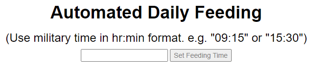
The first main chunk of code is for setting the time. I first write out the title of the section and a description of how to use the text box. Then, I use the input function with the type equal to text. This is for the box itself and allowing an input in that box. Then I add the id of "FeederSet", which is an ID I created for the text box. On the line below that, I created the actual "Set Feeding Time" button and used an onclick function to make sure the "setFeedingTime()" function only executes on the button click.
The image below shows what part of the interface the code represents.
<h1><b> Automated Daily Feeding</b><br></h1>
<h3>(Use military time in hr:min format. e.g. "09:15" or "15:30")</h3>
<input type="text" id="FeederSet">
<button onclick="setFeedingTime()">Set Feeding Time</button><br><br>
Next, I added a box where the web interface recieves the last set time from Firebase and displays it. There isn't really much to it here, I just created the header for where the time will be displayed. I set the id of this display box to lastSetTime. I talk more on how this works further below.
<h3>Last set feeding time:</h3>
<h2 id="lastSetTime">00:00</h2>
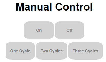
Then, I created the manual control buttons. I used the same steps as I did for the "Set Feeding Time" button," where I set each button to have its own respective id based on its function and used the onclick function to actually make it a button. I also added two custom CSS classes custombutton and custonbutton2 to make the buttons grey and rounded. I followed this guide to make custom buttons using CSS.
<h1><b>Manual Control</b></h1>
<button class="custombutton" id="OnButton" onclick="OnButton()">On</button>
<button class="custombutton" id="OffButton" onclick="OffButton()">Off</button>
...
<button class="custombutton2" id="OneCycle" onclick="OneCycle()">One Cycle</button>
<button class="custombutton2" id="TwoCycles" onclick="TwoCycles()">Two Cycles</button>
<button class="custombutton2" id="ThreeCycles" onclick="ThreeCycles()">Three Cycles</button>
This stuff is all for connecting to Firebase. I copied this from the class demo we did earlier in the semester and added in my Firebase config. I left the Firebase config here blank for privacy reasons, but the real code has the real Firebase info. There isn't any picture for what this represents on the web interfact because this is stuff that happens behind-the-scenes.
<!-- The core Firebase JS SDK is always required and must be listed first -->
<script src="https://www.gstatic.com/firebasejs/7.13.2/firebase-app.js"></script>

<!-- TODO: Add SDKs for Firebase products that you want to use
     https://firebase.google.com/docs/web/setup#available-libraries -->
<script src="https://www.gstatic.com/firebasejs/7.13.2/firebase-database.js"></script>
<script src="https://www.gstatic.com/firebasejs/7.13.2/firebase-analytics.js"></script>

<script>
  // Your web app's Firebase configuration
  var firebaseConfig = {
        apiKey: "",
        authDomain: "",
        databaseURL: "",
        projectId: "",
        storageBucket: "",
        messagingSenderId: "",
        appId: "",
        measurementId: ""
    };

    // Initialize Firebase
    firebase.initializeApp(firebaseConfig);
    firebase.analytics();

    // Get a database reference for the web interface
    var ref = firebase.database().ref("/");
These five lines are for calling the buttons in this script. I needed to do this because I created the buttons outside of this script, so I need to tell the interfact to be constantly checking for the status changes of these buttons. Think of it like a loop function, and these lines are what are checking the status of the buttons in that loop.
// make the buttons call their respective functions below
    document.getElementById('OnButton');
    document.getElementById('OffButton');
    document.getElementById('OneCycle');
    document.getElementById('TwoCycles');
    document.getElementById('ThreeCycles');
This set of code is for the last set time box. Firstly, I looked at this guide from Firebase on how to read data from Firebase and display it on a webpage, and secondly, I edited their first "Read data" example to fit my needs. Essentially what's happning is that the lastSetTime variable is being recieved from Firebase using the command snapshot, which takes a saves the current time value in Firebase. I then used the getElementById function to get the box with ID lastSetTime to then display the ["FEEDING TIME"]. I highly recommend checking out that guide I posted above, as it goes over pretty much everything on reading and writing on Firebase.
var lastSetTime = firebase.database().ref('/');
lastSetTime.on('value', (snapshot) => {
    const data = snapshot.val();
    console.log(data);
    document.getElementById("lastSetTime").innerHTML = data["FEEDING TIME"];
});
For setting the feeding time, I used the code below. Quite simply, I created a variable called "feedingTime" that stores the time data that's typed in the text box with the "FeederSet" ID. Then, the Firebase data point "FEEDING TIME" is updated with whatever the feedingTime is, which is the time typed in the text box.
   function setFeedingTime(){
        var feedingTime = document.getElementById("FeederSet").value;
        console.log("New feeding time set");
        alert("Feeding Time Set");
        ref.update({
            "FEEDING TIME": (feedingTime)
        })
    }
});
The "On" and "Off" button functions are super simple. When either button is pressed, the respective button function is called. So, for example, if the "On" button is pressed, then the onButton() function is called on, which I talked about earier. Then, there is a console.log function to display the function on the web page console and an alert function to give an alert from the web page. Finally, I use the ref.update function to update the status of "FEEDER STATUS" on Firebase to either "ON" or "OFF." When the status changes on Firebase, the data is sent to the Huzzah.
   function OnButton(){
        console.log("Feeder manually turned on");
        alert("Feeder Turned On Manually");
        ref.update({
            "FEEDER STATUS": "ON"
        })
    }

    function OffButton(){
        console.log("Feeder manually turned off");
        alert("Feeder Turned Off Manually");
        ref.update({
            "FEEDER STATUS": "OFF"
        })
    }
Finally, we have reached the end of the web page code. The last section is for the three cycles. But, since the code is basically exactly the same but with the cycle number changed, I'll only talk about the code for the first cycle. Similar to how the "On" and "Off" buttons work, the cycle buttons all work by having their function tag first be called by the web page when the web page buttons are pressed. Then there's the console.log and alert function. At the end, there's the ref.update function for chaning the "FEEDER STATUS" on Firebase to "ONE CYCLE." For the other cycles, this would be either "TWO CYCLES" or "THREE CYCLES." Then, when Firebase updates the "FEEDER STATUS," the data is sent to the Huzzah and is outputted by the respective function, in this case, the one cycle code is run.
   function OneCycle(){
        console.log("Feeder manually activated for one cycle");
        alert("Feeder Activated For One Cycle");
        ref.update({
            "FEEDER STATUS": "ONE CYCLE"
        })
    }
Click here to view a demo of the web interface page.
And that's it for the web interface HTML and JS code overview. Next, I talk about the final product and then end off with possible future improvements.
Final Product
The final fish feeder turned out great. I like the simplicity of the web interface and the feeder itself. Below are some videos and pictures of the fish feeder and some feeding demonstrations.
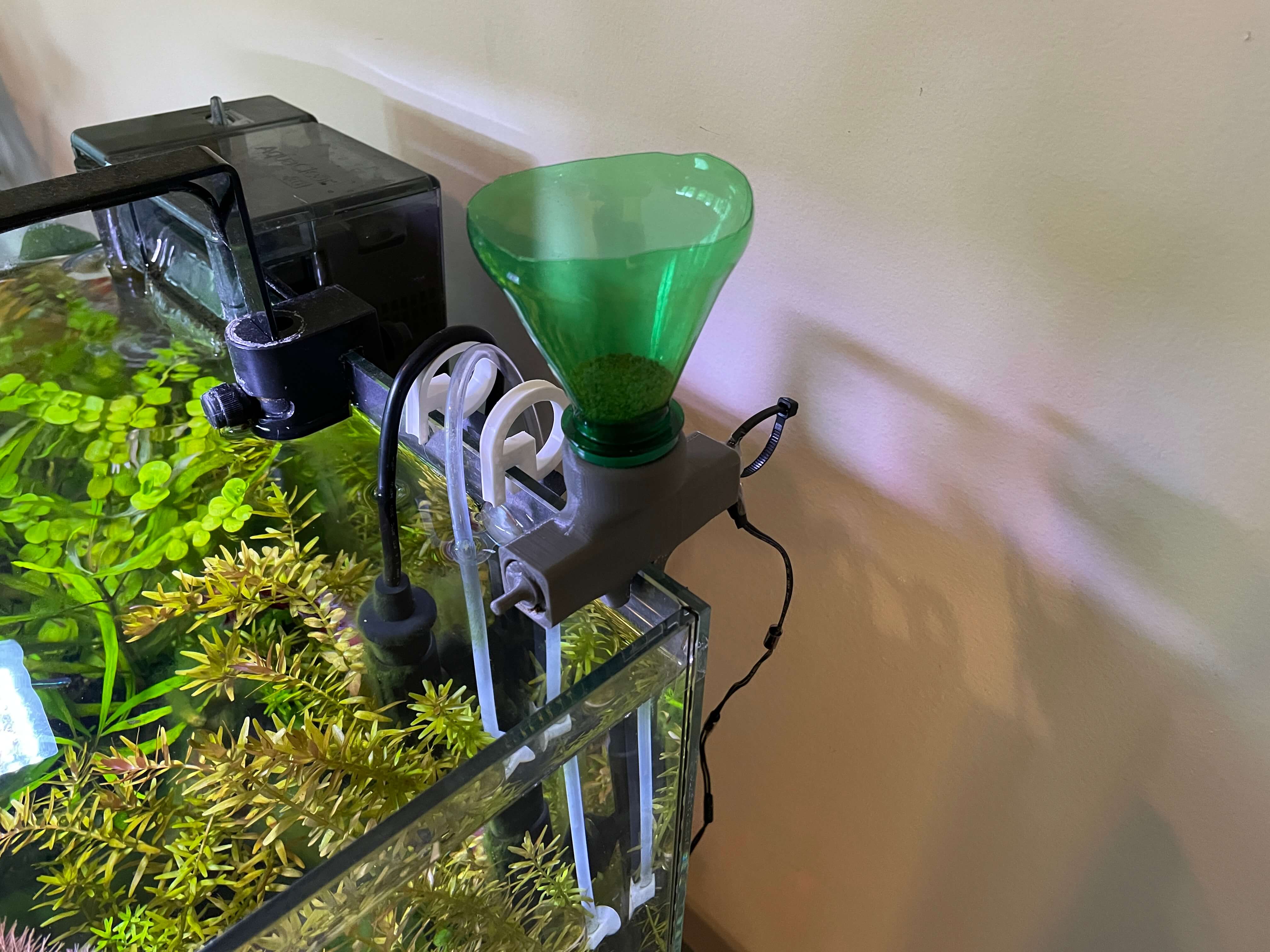
I mounted the feeder on the back side of the tank, next to the CO2 diffuser and water heater. I placed the electronics box right behind the tank with the red LED facing outwards. The electronics box was actually the perfect size for the edge of the table, which is good. Although there are the two black wires hanging off of the back, I can easily tape them to the back of the tank and they would be hidden because the background of my tank is black.
I think it looks pretty good on the back of the tank, as the back is now filled with aquarium components: the filter, water heater, light handle, CO2 diffuser, and now the fish feeder.
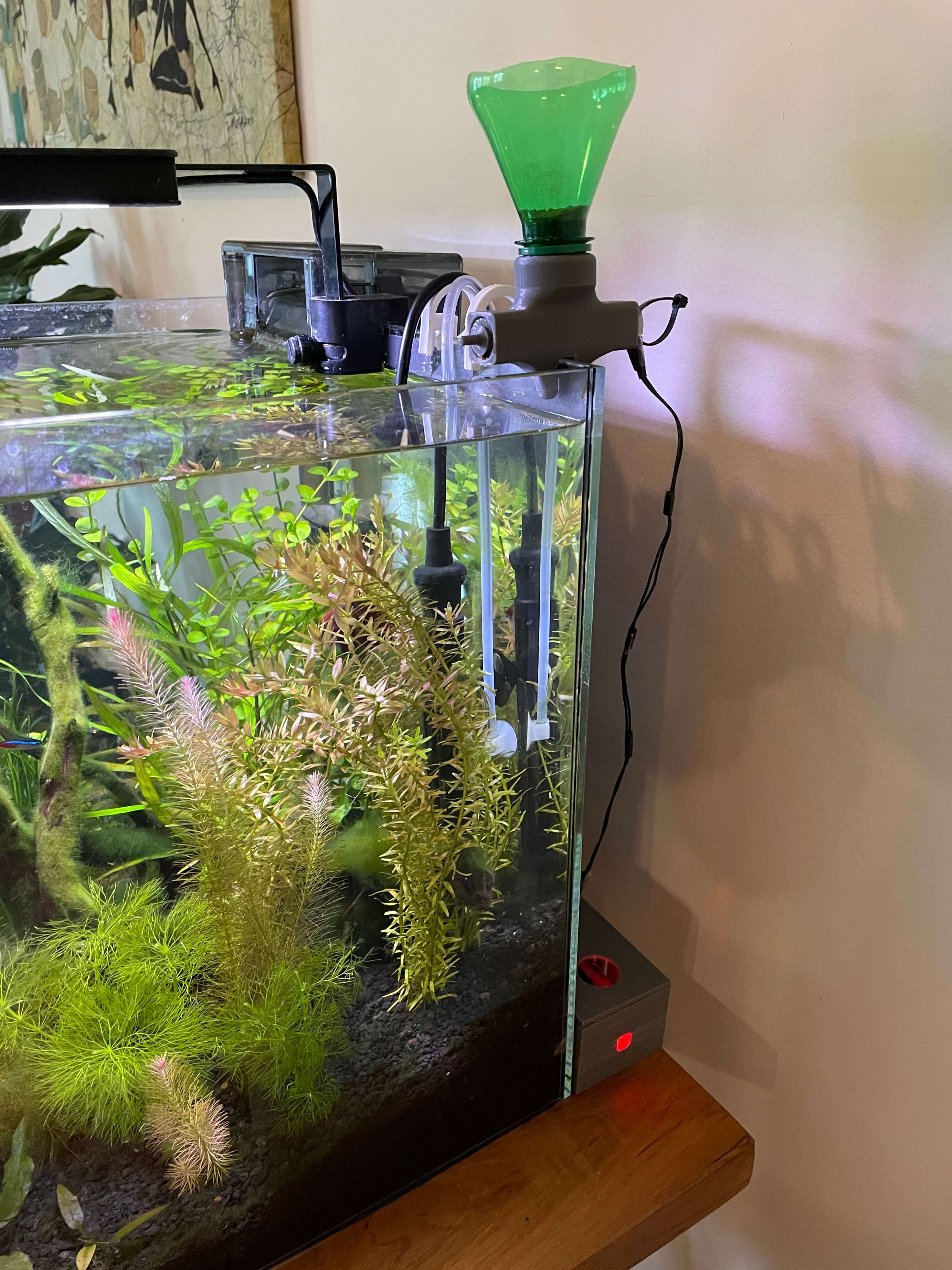
To attach the fish feeder to the back glass of the tank, I lightly screwed two M3 screws though the screw holes to create a clamp around the glass. The side image of the feeder and a video of the installation are shown below.
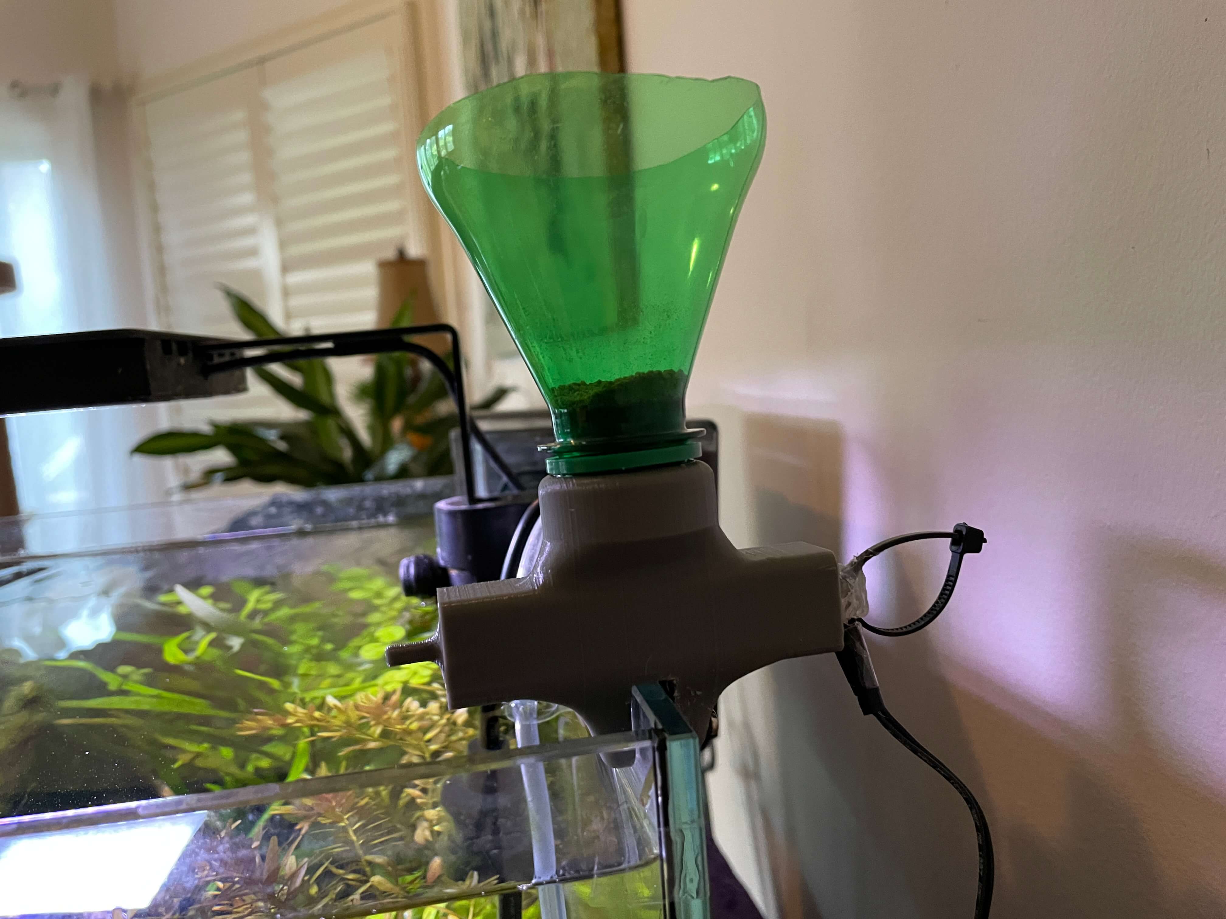
I made sure not to tighten the screws too much because, at the end of the day, I am screwing into glass and glass can break. There is also the black posterboard background that acts as somewhat of padding between the screw and glass.
The way I calibrated the delay amount for each cycle was by doing a lot of testing, and the end product was definitely worth it. The video below shows the feeding cycles and the image shows a large test of food quanity versus cycle count.
In the video, one thing to note is that when I clicked the "Two Cycles" button, it took some time before the feeder actually fed two cycles. This is actually a common occurence I found with using Firebase. I'm not sure why the problem exists, but sometimes, it just takes a little bit for the web interfact input is outputted on the feeder. On the contrary, when I clicked the "Three Cycles" button, it worked immediately.
In the cycles test, the food amount progressively increases with each cycle amount increase. This is exactly what I wanted and I found these feeding amounts to be sufficient for my fish.

The two videos below are the last two of the page. The first one is a complete assembly guide from scratch (for anyone wanting to make it) and the second is a demo of the manual pushbutton.
Future Improvements
There are three main improvements I would like to make in the future. One is adding a small TFT display above the LED indicator, another is to fix the connection delay issues, and the last is to add more functions to the web interface. I give a brief summary of each below.
My original plan for the electronics box was to have a TFT display above the LED indicator that would scroll throug the current time, set time, and feeding status. Unfortunately, I couldn't get my TFT display to work on either Huzzah or the Metro boards. This is something that is definitely possible, but I just have to buy a new TFT display because I'm pretty sure mine's broken.
The connection issue I'm talking about has to do with a delay between pressing a button on the interface and the fish feeder actually outputting that function. An example of this delay can be seen in the second video of the last section. There isn't always a delay, but when there is, it gets quite frustrating to work with the feeder. I don't know what the root cause of the issue is, though. I'm guessing it has something to do with the connection from the interface to Firebase because there isn't anything wrong with the hardware.
The last improvement I would like to make is adding more functionality to the web interface. One thing I think would be cool is specific times for specific days. This can be good for feeding the fish when you are at home to make sure everything is working fine. Another thing I can do is to select what type of food (large pellets, small pellets, dried bloodworms, etc) I have in the food holder and have the feeder automatically know how much the motor should spin to get the correct amount of food into the tank. This would be a great help because I wouldn't have to go into the code each time to adjust the delay for feeding because, as of right now, the feeder is only meant to be filled with these really small pellets. The delays wont work for larger pellets because they fill in the gaps between the screw thread more than the small pellets do, so they come out at a slower rate.